
Test Switch Wiring Diagram
No new schematics or wiring diagrams are required and the test plugs that are currently on the market can be used with testing equipment wired through the utsi. Plug a clock radio or light into the outlet.
Emergency Test Switch
Gm headlight switch circuit descriptions.

Test switch wiring diagram. 15 amp light switch wire nuts utility knife philips screwdriver wire strippers needle nose pliers we will go through the two primary configurations for wiring a light switch. Two technicians are discussing a wire harness construction: Flasher voltage input (voltage sent from flasher to turn signal switch).
Gfci electrical outlet wiring diagram. Disconnected or loose wires 3. Leviton 15 amp self test smartlockpro combo duplex guide light and tamper resistant gfci outlet white r92 gfnl1 00w the.
The cost of installing the test switch along with the cost of the larger meter base to hold the test switch is often times a deterrent. Be aware that these are general diagrams using standard test switches which may not. Not only will it help you attain your required final results.
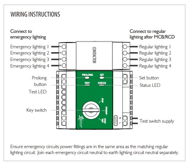
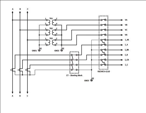
For wiring a switch, you must have these tools and equipment. Up to 6x units can be connected together, allowing up to 30 mains circuits to be monitored. Ft test switches have been an industry standard for years.
Can easily be connected to open type units. 13 pin gray connector : Test switches have been implemented for this reason.
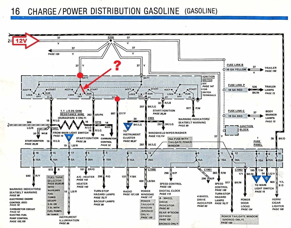
Then, rotate the switch to the start position and probe the module's white wire connector and ignition coil's battery terminal to examine the voltage. Technician a says that connector #1 is the male connector because the while plastic connector fits inside the connector #2. At times the cables will cross.
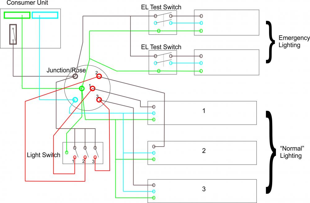
A clear understanding of the circuit and a wiring diagram are needed for effective diagnosis. Connect kit/unit as per wiring diagram (supplied). Multiple emergency test switches can be interlinked so that multiple emergency systems can be triggered at the same time when one or more lighting circuits fail.
Accelerator rod disconnected or loose: Diagnostic tools unpowered test light this tool consists of a 12 volt light with leads. All of the test switches on the market have the ability (when properly configured) to short the primary and secondary of the ct, and also isolate them from the control instrumentation, such as safety relays, which makes it safe to perform necessary testing and.
Here are the circuit descriptions of the wires that we'll be testing in this test article: Do the same at the ignition coil's battery terminal. Gm hei ignition distributor wiring diagrams and guide.
10 va @ 32 vdc alarm response time: Gm ignition switch wiring diagram. Be aware that these are general diagrams using standard test switches which may not match some utility.
Probe the red wire connection to test the voltage. Customer service al aspects of customer service including order status, delivery, and quality assurance are directly handled by. It is recommended that the emergency lighting discharge test unit/kit is connected on the same phase as surrounding normal lighting.
Test switches allowing for a quick and easy exchange. Diagram chrysler wiring diagrams easy simple gm free striking, size: Also, in the case of residences one could argue that they just do not use enough power to justify putting a large meter base and test switch on the wall because the meter will be changed out when all of the.
From it there is 3 wire cable that leads to a light which then connects to other lights controlled by their own switches. 1s wiring diagram 1 ph, 2 wire glems would like to thank and acknowledge the use of the following meter connection diagrams from dr. 10 va @ 32 vdc reset switch:
Cam not activating micro switch: Use a logical sequence of testing to find the trouble. I zl ii i i ii i i fo 0;
With such an illustrative guide, you will be able to troubleshoot, avoid, and full your projects without difficulty. 17 pin black connector : General motors ignition switch used in chevrolet and pontiac cars from 1969 through 1994.
Rear right turn signal output. Technician b says that connector number #2 is the male connector because it has male terminal pins. Each part should be placed and linked to other parts in particular way.
After the trouble is fixed, make sure the circuit works correctly. April 16, 2020 · wiring diagram. Power to the switch in the first step, the power comes to the switch and then travels to the light.
The circuit and the switch are faulty if there is not voltage. How to test the gm distributor mounted ignition module. Rear left turn signal output.
Wiring diagram of the emergency test switch assembly.
Emergency Test Switch Installation Ektor UK

The Lazy Man's Method to Test the Ignition Switch Ford Truck Enthusiasts Forums

So How Can I Test A Relay?
Wiring A, Switch, Emergency Lighting Cleaver Simple Wiring Diagram, Emergency Light, Switch


How do I test the 7 prong ignition switch, 1 day, yes, no
17 Fresh Ct Test Switch Wiring Diagram
Test wiring diagram IH8MUD Forum
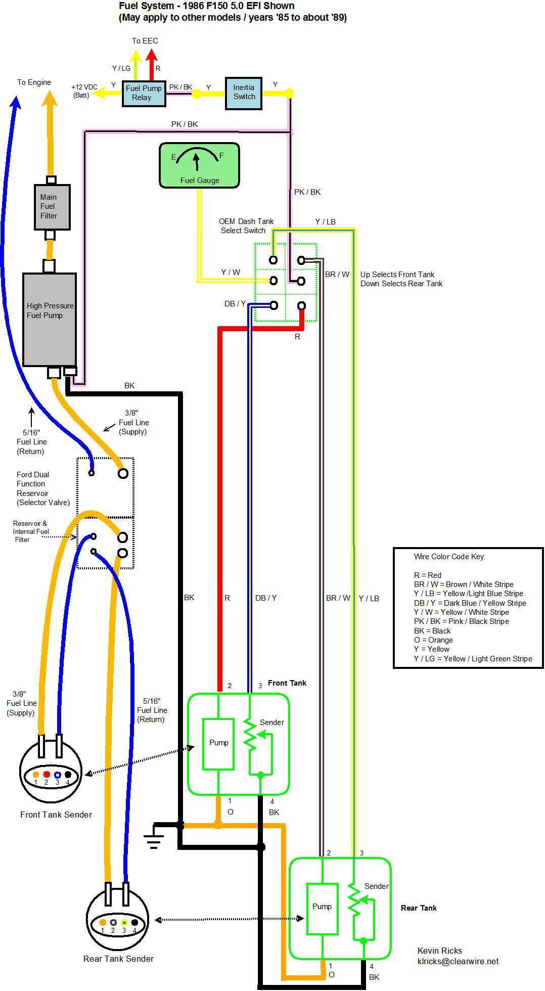
Rear Tank Reading Empty Test Fuel Selector Switch Ford Truck Enthusiasts Forums
Relay Test Switches Utility Products
Plugin Mains Switch Drop Leads flex7
Wiring up/Testing of Emergency Lighting Emergency Lighting Safelincs Fire Safety Forum
Emergency Test Switch Installation Ektor UK

21 Lovely Emergency Light Key Switch Wiring Diagram

Emergency Test Switch Installation Ektor UK

Plugin Mains Switch Drop Leads flex7
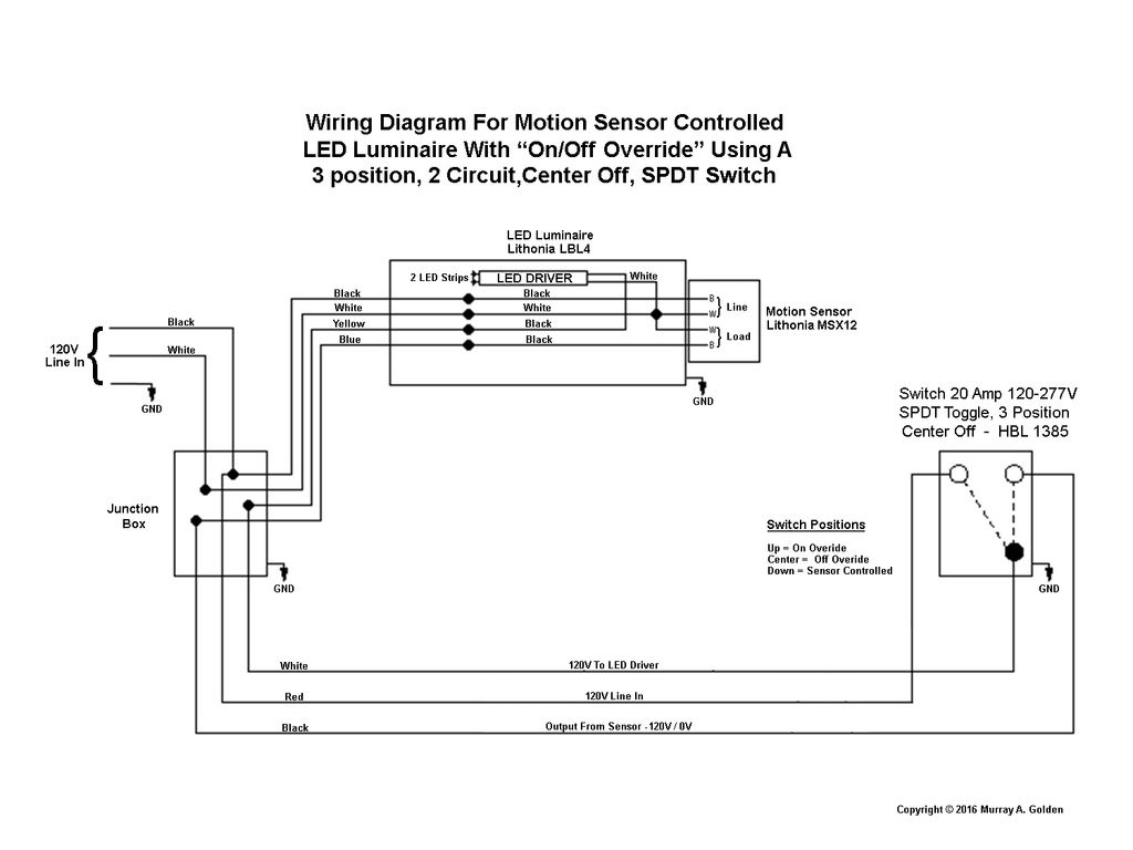
Motion Sensor Light Switch Wiring Diagram Cadician's Blog

20 Inspirational No Volt Release Switch Wiring Diagram
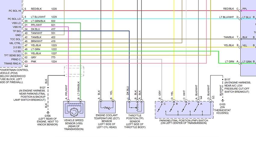
How to Test a Neutral Safety Switch in Under 15 Minutes
Plugin Mains Switch Drop Leads flex7
